Cisco ISE 3.1 added a new feature called Zero Touch Provisioning (ZTP). Not only does it allow you to create a configuration file in which the ISE node can be configured (IP, hostname, DNS, etc.) it can also automatically install any hot fixes or patches immediately after it is set up. Outside of the normal VM configuration, there are two requirements for ZTP:
- A serial port is needed for the VM. If the OVA is used to deploy the VM image, it does not automatically configure a serial port so you will need to manually configure one just like a KVM install using the ISO.
- A ZTP configuration file that will be mapped to a 2nd virtual CD-ROM.
The serial port is a standard port. There is no special configuration. The reason it is needed is because the ZTP process utilizes the serial console. It is also required in order to monitor the automated install logs because the output doesn’t show in the console. Output after the setup prompt will show through the standard VM console.
The ZTP file itself is an IMG file created using a script and configuration file. Cisco provides a template for both in the Cisco ISE 3.1 admin guide linked above. The script requires RHEL, CentOS or Ubuntu Linux to run. You only edit the configuration file with the settings required. The bash script should be left as is.
Lab setup
Proxmox Virtual Environment 7.0 – This is my Linux KVM server
Cisco ISE 3.1 ISO – Must use the ISO for Linux KVM install. Includes 90-day license.
Laptop running Xubuntu – Lightweight Ubuntu based client I’ll use for creating the ZTP configuration file and deploying the ISE node VM.
Configuration
The setup for the VM is straightforward. I configured the resources as a small VM with the following recommended Linux KVM settings:
- 16 vCPU with 16000 MHz reservation (1000 MHz per core)
- 32 GB of RAM
- 300 GB of hard drive space (pre-allocated, RAW)
- Disk bus: VirtIO
- Cache mode: None
- I/O mode: Native
- One NIC (VirtIO)
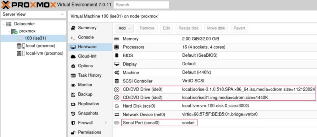
- Two (2) CD-ROM devices
- One will be set to the ISE 3.1 ISO. The other will be for the ZTP configuration image
- OS Type set to Linux 5.x – 2.6 Kernel
- Serial port added (required to monitor ZTP log status)
- Everything else left at default settings
You can also configure the VM with 4 vCPU and 16 GB of RAM for a small lab server. One thing to note is the Proxmox Linux KVM will not be seen as supported hardware. This is due to the ISE installation program not seeing it as a Linux KVM. To correct this, perform the following if you’re using Proxmox (may be the same for others):
- Go to [VM] > Options > SMBIOS.
- Set the Product field to KVM.
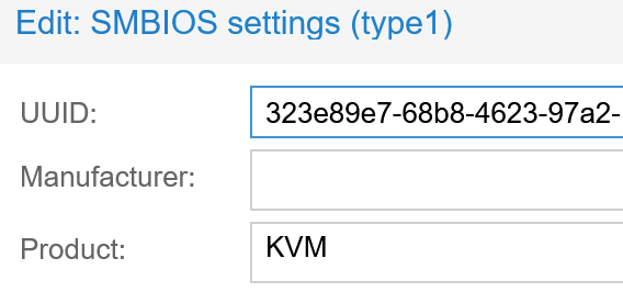
Product is set to KVM.
Next up is creating the ZTP configuration image file. As noted, Cisco provides a shell script and a configuration file example in the Cisco ISE 3.1 installation guide. The shell script must be created and enabled for execution (chmod +x [filename].sh). There isn’t any need to edit the shell script but you will need to modify the configuration file for the node you will be deploying. Multiple nodes? Multiple files required.
My configuration file has the the basic info (hostname, IPv4 settings, DNS, etc.) and I stripped out the following as I don’t use it:
- IPv6
- Secondary and Tertiary DNS
- This is my lab and so it only has 1 DNS server at this time
- Repository, patch, and hot patches section
- The repository is for that node only in order to install a patch or hot patch once the initial configuration/setup completes. This is not the same as the repository you configure from the PAN when the node is part of a deployment.
hostname=ISE31
ipv4_addr=172.16.100.26
ipv4_mask=255.255.255.0
ipv4_default_gw=172.16.100.1
domain=securitydemo.net
primary_nameserver=172.16.100.40
primary_ntpserver=0.north-america.pool.ntp.org
# secondary and tertiary are optional
secondary_ntpserver=1.north-america.pool.ntp.org
tertiary_ntpserver=2.north-america.pool.ntp.org
timezone=UTC
ssh=true
username=admin
password=ISEc0ld
#services - optional
ers=true
openapi=true
pxgrid=true
pxGrid_Cloud=true
The majority of the configuration file is what you would normally enter manually during the setup phase. The services, repository, patch installation, and hot patch installation would be configured post installation. So you can see where this can save you a few steps.
With the shell script created and set to executable, and the configuration file in place (same directory), it’s time to make the ZTP image file. The command is ./[shell-script] [conf file] [image file]. For me, the commands were:
bradj@secdemo-xubuntu:~/ISEZTP$ chmod+x create_ztp_image.sh
bradj@secdemo-xubuntu:~/ISEZTP$ ./create_ztp_image.sh ise31.conf ise31.img
I named the configuration file the same as the hostname of the node so it would be easier to keep up with if this was a multi-node deployment. The resulting image file will also have the same name as the node hostname. I first ran the script using my regular account. The output showed errors mounting and unmounting the temporary directory that is created by the script.
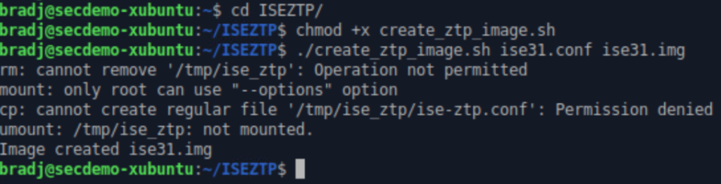
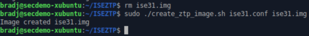
I received errors because the user account doesn’t have root privileges for the mount command. Even though the image file was created, it is not formed properly. Using that file would result in the setup program throwing an error about the ZTP configuration being invalid. I deleted the invalid image file and used sudo to run the script.
Here you can see where I uploaded the Cisco ISE 3.1 ISO and the newly created ZTP image file to the Proxmox VM server.
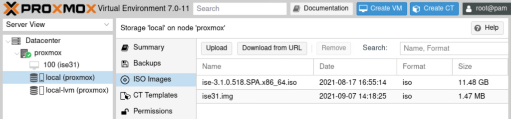
With the files uploaded, I attach them to my ISE VM as CD-ROM 1 (ide0, ISE ISO) and CD-ROM 2 (ide2, ISE ZTP image). Note the serial port was also added to the hardware configuration.
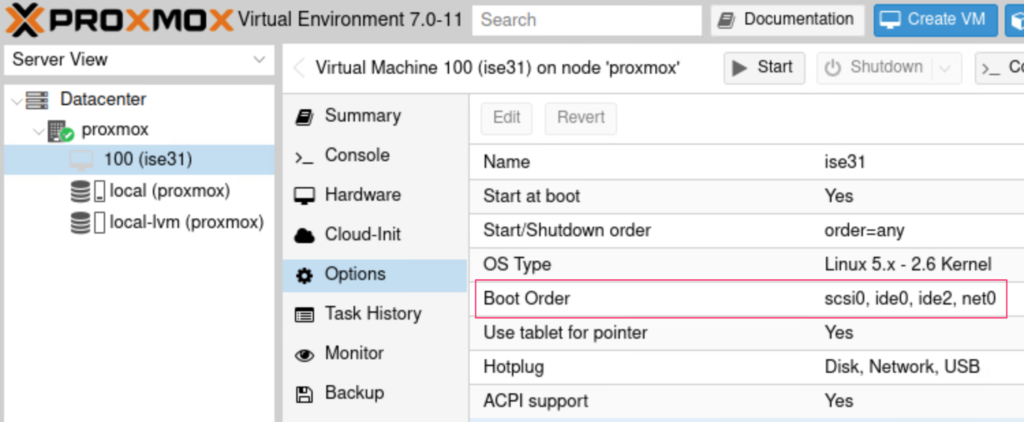
I set the boot order so that scsci0 (HDD) was first followed by ide0 (ISE ISO).
Time to boot up the system and install ISE! I opened a regular console connection (noVNC) and a serial connection (xterm) after turning the VM on. You can just hit Enter at the boot option screen.
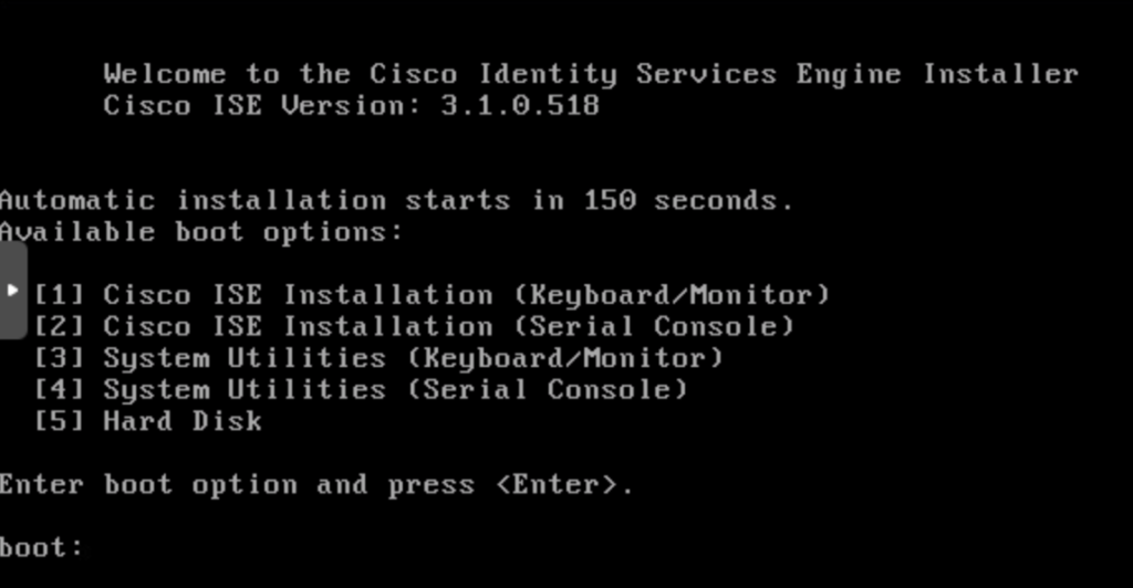
You should see the following in the serial console (not the regular console) after the normal boot process finishes and the installer starts. This will indicate that the valid ZTP configuration file was found as well as showing the VM host is detected.
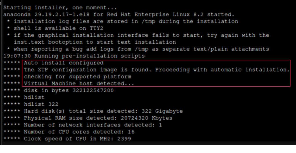
The installation process can take a while (30 minutes-ish). Once it completes, the node will reboot and go through the setup phase. That’s where the ZTP image file comes into play. You would normally have to type in setup and go through all the entries. Not with the image file mounted. That will take care of starting the setup and inputing the configuration. You will see all of the information automatically put in via the console and you can monitor any logs/errors in the serial console.
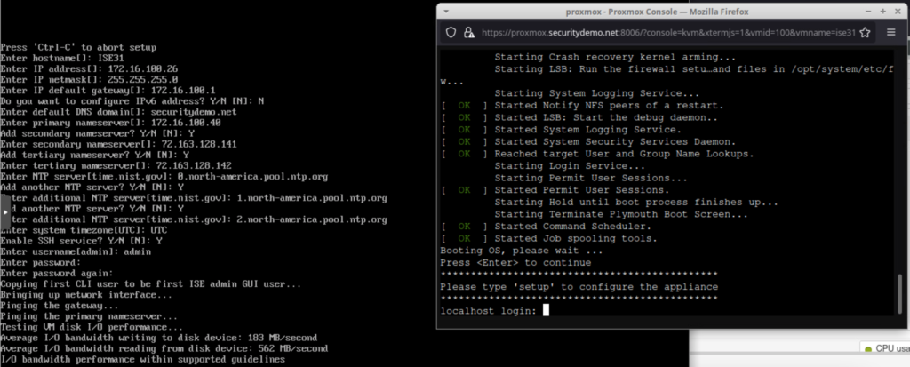
Screenshot showing VM console (right) and VM serial console (left) output during setup using ZTP image.
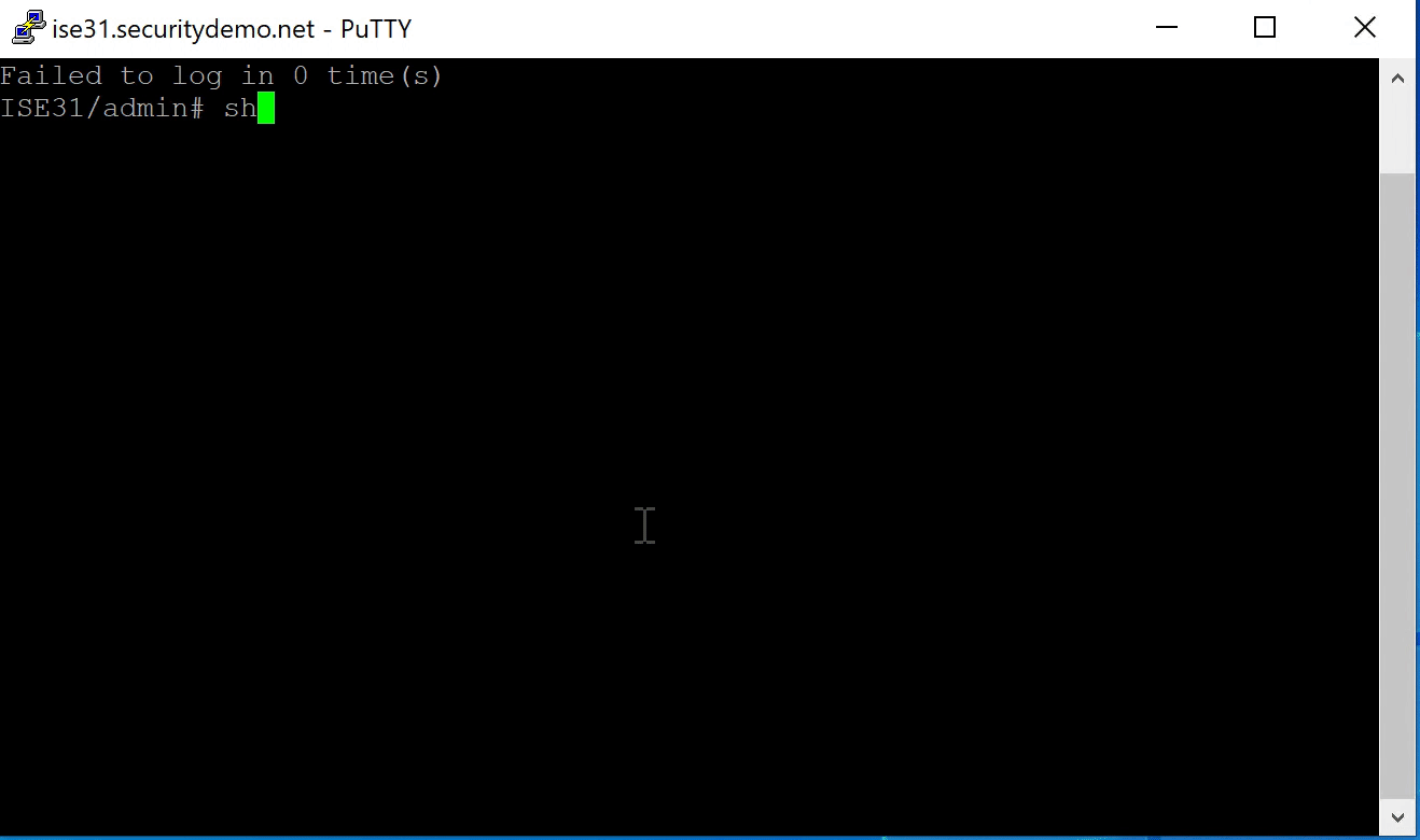
That’s it. The ISE node will go through the rest of the configuration automatically. It will reboot once the database and application is configured. If you configured a repository and hot patch or regular patch installation, that will take place after the node reboots and all services start. The node is ready for deployment once this is complete and all services are online. Be sure to eject the files from the virtual CD/DVD drives.
Watch the installation logs in the serial console. They will indicate if there is bad or incorrectly formed ZTP image file.
Questions
What happens if you have the wrong configuration (like duplicate NTP servers) and it errors out during the setup?
Not a problem. Simply turn the VM off, build a new ZTP image file using a corrected configuration file, attach the updated ZTP image to the VM, and turn the VM back on. The setup will begin again using the new configuration file. The only time this won’t work is if it is past the configuration to where you see the warning Do not use ‘Ctrl-C’ from this point on…. If the node fails after that, you will need to correct any errors and reload the node from the beginning.
What if I don’t want to mount two CD-ROM drives or want to use the OVA?
That works as well. Using a single CD-ROM with the ISO mounted or the OVA (VMware only), you can install Cisco ISE as usual. When you get to the point where you type in setup, turn the VM off, eject the ISO (if not using the OVA), attach the ZTP image file, and boot the VM. The setup program will detect the mounted ZTP configuration file and go from there. Using two CD-ROM entries just makes the process a little smoother so you don’t have to do the shutdown/mount/restart.
What if we don’t have a VM and want to use an SNS-36xx appliance?
You still have the option of using ZTP! You can:
- Map the ZTP image file first and then the ISO in the virtual KVM (CIMC) or
- Map the ISO in the virtual KVM, install ISE, shut down the host once the setup prompt shows, map the ZTP configuration file, boot the host, and automatic configuration will go from there.